In 1896, Carl Emanuel Nilsson, Harry Nilsson's great-grandfather, patented a "Stage Apparatus" for producing an "aerial ballet" where dancers appear to float and move in mid-air.
Nilsson applied for the patent on January 17, 1895. The USPTO granted the patent (Number 558,413) on April 14, 1896. The patent expired on April 14, 1913.
To all whom, it may concern:
Be it known that I, CARL E. NILSSON, of New York city, in the county and State of New York, have invented a new and improved Stage Apparatus, of which the following is a full, clear, and exact description.
My invention relates to improvements in stage apparatus; and the object of my invention is to produce a simple apparatus which is adapted for use in producing an aerial ballet, and which, by being arranged above a stage, is capable of supporting ballet-dancers in mid-air, and may be conveniently and easily manipulated, so as to give to the aerial dancers the appearance of floating in the air or moving laterally and also of moving up and down.
A further object of my invention is to produce an apparatus of this character, which is very simple and strong and little likely to get out of order. To these ends my invention consists of certain features of construction and combinations of parts which will be hereinafter described and claimed.
Reference is to be had to the accompanying drawings, forming a part of this specification, in which similar figures of reference indicate corresponding parts in all the views.
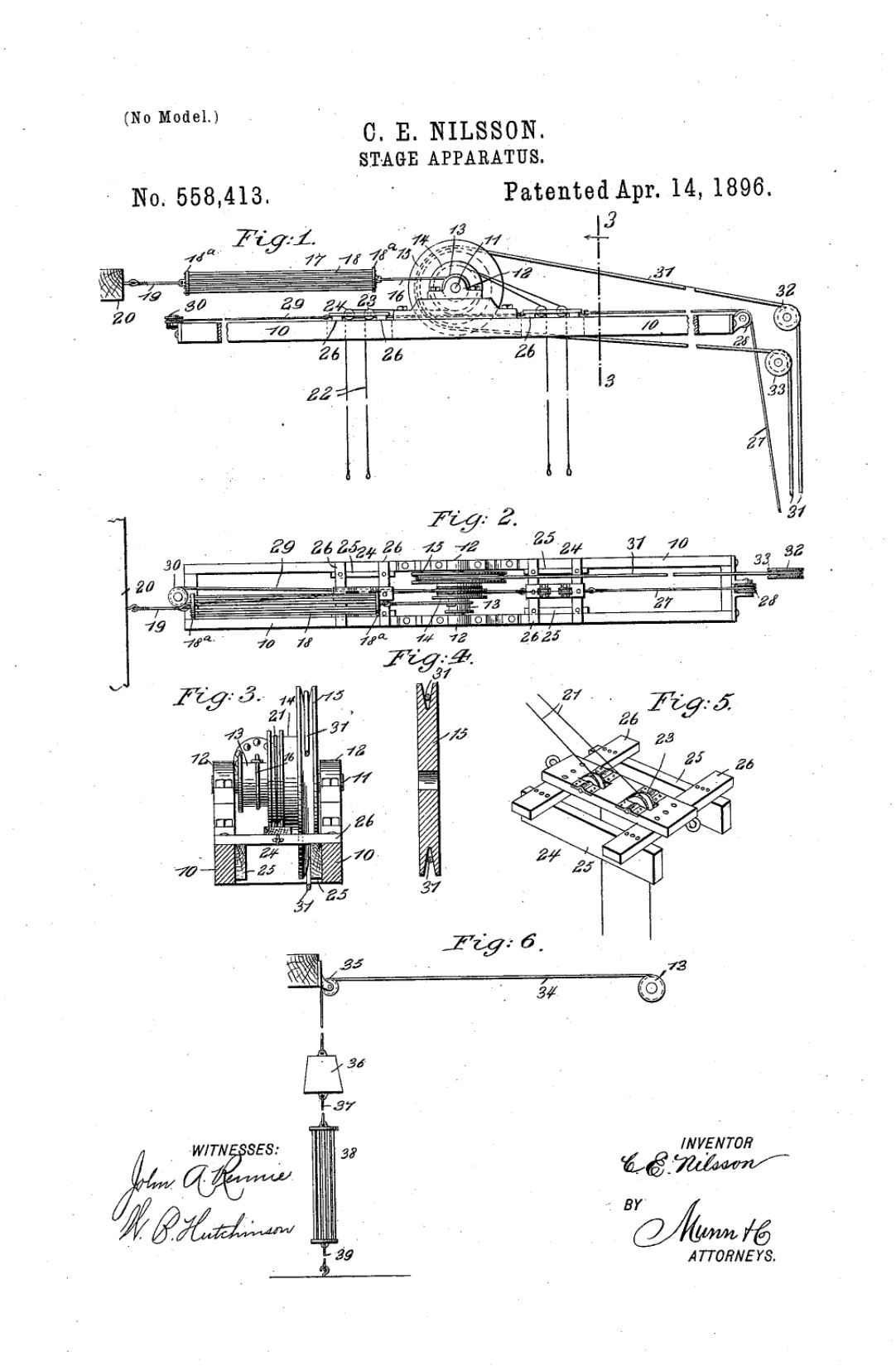
Figure 1 is a broken side elevation of the apparatus embodying my invention. Fig. 2 is a plan view of the apparatus. Fig. 3 is a cross-section on the line 3 3 of Fig. 1. Fig. 4 is a detail cross-section of the largest part of the cone-pulley. Fig. 5 is a detail perspective view of one of the slides which moves on the main frame, and Fig. 6 is a broken detail view of a modified form of counterbalance which is adapted to be used in connection with the cone-pulley.
The apparatus is provided with an elongated frame 10, which is adapted to be supported over a stage in any convenient way, and arranged centrally and transversely on the frame is a shaft 11, which turns in suitable boxes 12, and the shaft carries a cone-pulley formed of the parts or pulleys 13, 14, and 15, these being arranged so as to turn together, thus forming practically a single cone-pulley. To the smaller part or face 13 of the pulley a cord or cable 16 is attached, and this connects with a counterbalancing-spring 17' formed of a series of rubber strings 18, which are fastened to the heads 18" of the spring, and the spring 17 connects by a cord or cable 19 with an adjacent support 20. It follows that when the cone-pulley is turned in one direction, as hereinafter described, the cord 16 will be wound on the part 13 of the cone-pulley, thus stretching the spring, and the proper tension on the cone-pulley is thus maintained, and the pulley is by the spring returned to normal position, as hereinafter described.
It will of course be understood that any other suitable spring may be substituted for the spring 17 but the rubber spring is preferably employed.
To the middle section 14 of the cone-pulley wires 21 and 22 are attached, these being arranged in pairs and attached to the pulley so that they may extend from opposite sides, as shown in Fig. 1, one being wound over the top of the pulley and the other from the bottom, so that the wires may be simultaneously wound or unwound without interfering with each other. These wires extend outward and downward over guide-pulleys 23 in the slides 24, which move on the frame 10 on opposite sides of the cone-pulley, and the wires terminate in loops, hooks, or other devices, which enable them to be conveniently fastened to the corsets of the ballet-dancers or to other parts of the clothing to suspend the said dancers. The wires are arranged in pairs, so that a number of wires may be connected with each dancer, and thus if one wire breaks the other will support the dancer and thus pre vent her from being injured. The wires are made of good material, so that they may be small enough to be invisible to the spectator and yet strong enough to safely support the dancers.
The slide 24 is provided with side pieces 25, but toward the opposite end of the frame, the two slides are connected by a cable 29, which, in order to give the right direction to the second slide, is passed around a guide-pulley 30, which is placed horizontally on one end of the frame 10. It will thus be seen that by pulling on the cable 27 both slides are moved toward the ends of the frame 10, and when the pulling strain is removed from the cable 27 the weight of the wires 21 and 22, together with the weight suspended on the wires, is sufficient to return the slides to their inner position.
The largest part of the cone-pulley is the part to which power is applied to turn the pulley backward and forward, and this portion of the pulley is preferably grooved, so as to have the necessary friction on the cable 31, which runs over the pulley and extends outward and downward over guide-pulleys 32 and 33 to a point where it may be grasped from the stage, and by pulling on the cable and moving it backward and forward the cone pulley is moved as desired, and when the cone pulley is moved it winds or unwinds the Wires 21 and 22, and so raises or lowers the dancers suspended by the said wires, thus giving to the dancers the appearance of dancing in the air.
It will be seen from the above description that by suspending the dancers from the wires 21 and 22 and then moving the cables 27 and 31, as described, the slides 24a may be moved and the cone-pulley revolved, so as to give to the dancers the necessary lateral and vertical movements to cause them to simulate dancing, and the tension spring connected with the cone-pulley takes up all the slack wire and causes the apparatus to work smoothly and easily.
In some cases it may be desirable to have a dead-weight, which serves, in a measure, as a counterbalance, and this may be arranged as shown in Fig. 6, where the cable 34:, which connects with the section 13 of the cone-pulley, passes over a guide-pulley 35 and is attached to a weight 36, which connects by a cable 37 with a spring 38, like the spring 17 already described, and the spring 38 connects by a cable 39 with the floor or other rigid support.
Having thus described my invention, I claim as new and desire to secure by Letters Patent -
1. An apparatus of the kind described, comprising a pulley, movable guide-pulleys on opposite sides of the main pulley, means for simultaneously moving the guide-pulleys toward and from the main pulley, wires or ropes secured to the main pulley and extending over the said movable guide-pulleys, and means for operating the main pulley, substantially as described.
2. An apparatus of the kind described, comprising a pulley, a counterbalance connected with the said pulley, sliding guide pulleys on opposite sides of the main pulley, means for simultaneously moving the guide pulleys toward and from the main pulley, wires or ropes secured to the main pulley and extending down over the guide-pulleys, and means for operating the main pulley, substantially as described.
3. An apparatus of the kind described, comprising a pulley, slides on opposite sides of the pulley, guide pulleys in the slides, wires or ropes secured to the pulley and extending over the guide-pulleys, and means for simultaneously moving the slides toward and from the pulley, substantially as described.
4. An apparatus of the kind described, comprising a supporting-frame, a pulley journaled thereon, slides on the frame and on opposite sides of the pulley, a cable connection between the slides whereby they are simultaneously and oppositely moved, suspending-wires connected with the pulley and extending over the slides, a cable mechanism for turning the pulley, and a counterbalance also connected with the pulley, substantially as described.
5. An apparatus of the kind described, comprising a supporting-frame, a cone-pul ley journaled thereon, sliding guides on opposite sides of the cone-pulley, means for simultaneously moving said guides toward and from the said pulley, a counterbalance connected with one section of the cone-pulley, suspending-wires secured to the second section of the pulley and extending over the said sliding guides, and a cable connected with the third section of the pulley to turn it, substantially as described.
CARL E. NILSSON.
Witnesses
ALFRED LURCOTT, O. SEDGWICK.


")


")


